 EFFECT
OF PUMPING ON GROUND-WATER DIVIDES IN THE DEEP SANDSTONE IN SOUTHEASTERN WISCONSIN EFFECT
OF PUMPING ON GROUND-WATER DIVIDES IN THE DEEP SANDSTONE IN SOUTHEASTERN WISCONSIN
Pumping has moved the regional ground-water divide in the deep part of the
system westward almost entirely outside the seven-county southeastern Wisconsin
region.
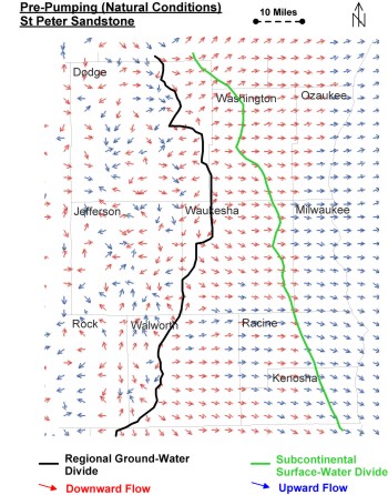
The regional ground-water divide marks the boundary east of which deep ground
water is tributary to Lake Michigan. Even before pumping this divide was far
to the west of the subcontinental divide that marks the Great Lakes watershed
boundary.
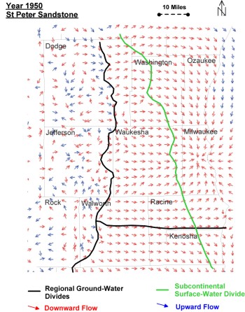
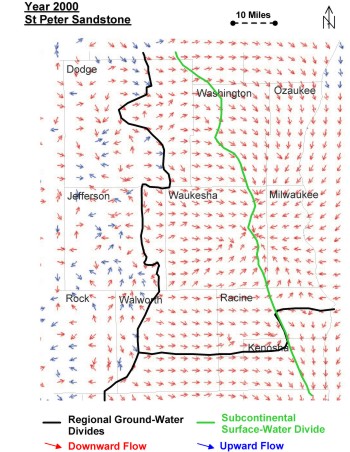
The figures below show the positions of the regional ground-water
divide in the deep part of the flow flow system for 1950 and 2000 relative to
its predevelopment position under natural conditions. In 1950, the regional flow
in the deep sandstone aquifer converged on the pumping center under Milwaukee
. By 2000, flow paths converge under eastern Waukesha County . Over that time
the regional ground-water divide has moved from Waukesha County westward about
10 miles into Jefferson County , a location 27 miles from the subcontinental
divide at the western edge of the Lake Michigan watershed basin. This displacement
of the divide in response to pumping is directly related to the increase in leakage
to the deep part of the flow system in areas where the Maquoketa shale is absent.
NOTE that the regional ground-water divide has moved west over
time, but that deep ground water that was formally tributary to Lake Michigan
now flows to pumping centers in Wisconsin and Illinois.
The flow-direction plots for the St. Peter Formation, representative of the
deep flow system, also show the changing location of the ground-water divide
between a regional ground-water system centered in southeastern Wisconsin and
another centered in northern Illinois. The model shows that in 1950 the divide
was located along the Kenosha/Racine County boundary. Increases in northern Illinois
pumping after 1950 moved the divide north into eastern Racine County, but the
development of local cones of depression around Union Grove moved the divide
south in western Racine and in Walworth Counties. While northern Illinois pumping
decreased overall in the 1990s, the 2000 divide is still north of the 1950 boundary
in some places.
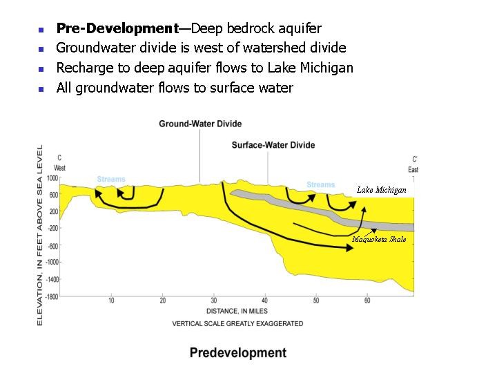
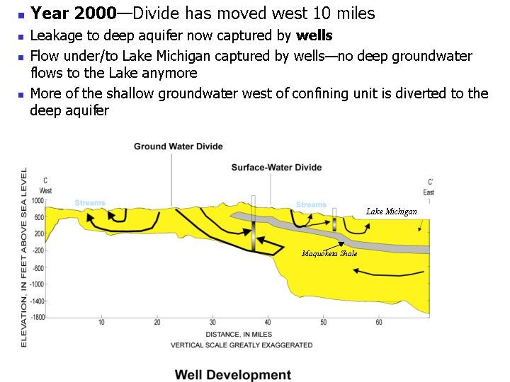
Cross sections show the relation of the changing ground-water
divide to three elements that control the regional flow system:
- the shale that confines the deep sandstone,
- Lake Michigan that served as a regional sink under natural conditions, and,
- the pumping centers that capture flow under current conditions:
The dramatic changes evident in the deep flow pattern between pre-development
and 2000 are not reflected in the shallow part of the flow system. Most of the
shallow ground water continues to discharge to local water bodies over short
flow paths. However, less ground water than before discharges to streams and
lakes; a greater fraction now leaks downward in response to the demand from wells.
Summing up:
return to top
|